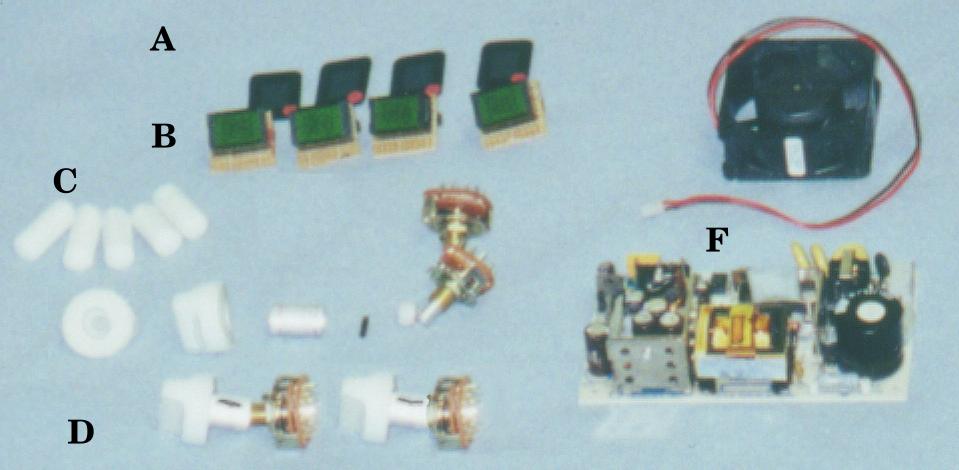
This is a shot of the controls and displays, the power supply(F) and fan(F). The switches at (D) are:O.S.(1-5), Cartridge(0-3), Floppy number(1-4), and Floppy write(norm, never, always, busy). I was going to program the LED displays(B)(A are the tinted cover lens) using diodes, but since I couldn't find diode arrays, I have no way of programming Pals or Gals, and I didn't want to do 200+ holes/solder connctions, I decided that I would use a PIC micro-controller instead. Another advantage is that it is easily changeable and I can have it do some display things that would require more I.C.s.
Note that each switch pulls out for use, then pushes in to be flush with the front. Each switch has a knob, sleeve with a slot, a pin, a spacer, and switch with a hole for the pin. The rods at (C) are for push button switches.